
System Level Integration of vECUs
🚗 Understanding the Vehicle Simulation Setup
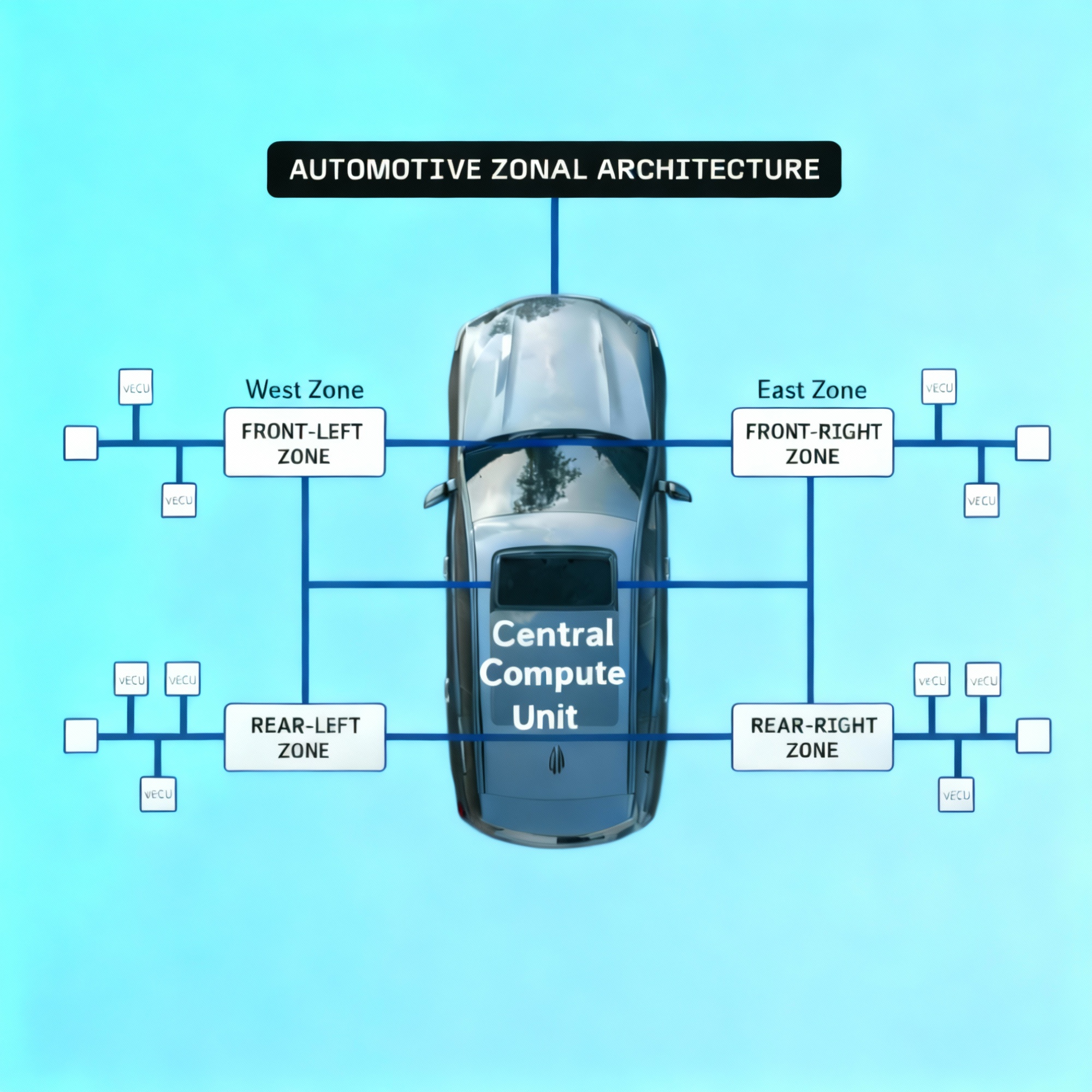
This document describes how we set up a comprehensive simulation environment for an automotive system. The goal is to make it easy to test and modify the software of virtual Electronic Control Units (vECUs) without having to constantly rebuild the entire vehicle’s electronic system model.
The Central Simulation Platform
We use a central simulation environment (like VEOS or NI Veristand) as the hub. This platform contains the Plant Models (which simulate the car’s physical behavior, like the engine or chassis) and manages the bus and communication network that connects everything.
How Virtual ECUs (vECUs) are Defined
Each vECU in the simulation is a clear, isolated unit. Their definition includes:
- Bus signals: The specific data they send and receive over the network.
- Diagnostic channels: How we check their health and functionality.
- Calibration and timing requirements: Settings and time constraints for their operation.
- The orchestrator handles the necessary scheduling of tasks and message routing between different vECUs.
Key Concept: Decoupling the Architecture
The vehicle’s overall Electronic/Electrical (E/E) architecture is treated as a separate, distinct model.
- Why this matters: If you need to add, remove, or change the location of vECUs (scaling), you only modify the E/E architecture model. You don’t have to rewrite the software inside the individual vECU models. This keeps the vECU software independent and reusable.
- How it works: We use the AUTOSAR System Description file (ARXML) as the single, authoritative source. This file defines all functions, signals, networks (CAN, Ethernet, FlexRay), and which ECU handles which functions. This ARXML file is your vehicle E/E model.
Building the vECU Software
For each vECU:
- We generate an ECU Extract ARXML. This is a small file derived from the main System Description, containing only the Software Components, signals, PDUs (Protocol Data Units), and communication matrix relevant to that specific ECU.
- This extract is then fed into the vECU Build process to configure and compile its software.
Communication and Signal Mapping
Inter-ECU communication is managed centrally:
- All inter-ECU communication is handled within the bus/network simulation layer of the central platform, rather than being managed separately by each vECU.
- The signal definitions and how they map to the network buses are defined just once at the “system definition” level (in the master ARXML). The simulation tool (like VEOS) then uses this definition to automatically map the vECU software ports to the correct bus signals.
Scaling the Simulation (15–25 vECUs)
To handle a large number of units (15 to 25 vECUs) efficiently:
- We use process or container isolation (e.g., Docker containers). Each vECU (or a small group) runs in its own separate operating system process or container.
- A central controller is then responsible for synchronizing time and communication across all these isolated processes, making them behave as one coherent system.
Configuration and AUTOSAR Compliance
Consistency is key. All 15–25 vECUs must be configured in exactly the same, reliable way:
- They are all consistently derived from the AUTOSAR ECU Extract ARXML.
- This ensures that the COM (Communication Stack), PDU routing, and RTE configuration are identical and correct across all units, perfectly matching the overall vehicle architecture defined in the system description.
AUTOSAR Standards
AUTOSAR (2022) Layered Software Architecture, AUTOSAR EXP LayeredSoftwareArchitecture, R22-11.
AUTOSAR (2021) Specification of ECU Configuration, AUTOSAR TPS ECUConfiguration, R21-11
AUTOSAR (2022) Software Component Template, AUTOSAR TPS SoftwareComponentTemplate, R22-11.
Commercial Tools & Platforms
dSPACE (2025) VEOS – Platform for PC-based simulation of models and ECU network simulation.
ETAS (2025) VECU-BUILDER V1.8 User Guide.
RemotiveLabs (2025) Virtualize entire vehicle platforms for early integration testing.
Synopsys (2025) Silver: Software-in-the-Loop Solution for Virtual ECUs.
Research & Industry Papers
Urbina, M. et al. (2015) Simulation Environment based on SystemC and VEOS for Multi-ECU Systems, CIT 2015.
Amazon Web Services (2023) Simulating Automotive E/E Architectures in AWS – Part 1: Accelerating the V-Model.
Amazon Web Services (2023) How BMW uses AWS to scale and automate SDV with virtual ECUs.
Container & Timing Research
Paul, A. et al. (2019) Virtualization of Industrial Real-Time Networks for Containerized Controllers, PMC, 6832656.
Beningo, J. (2024) CEC Beningo 2024 Session 2: Docker in Automotive Test Automation, DesignNews DigiKey Archives.